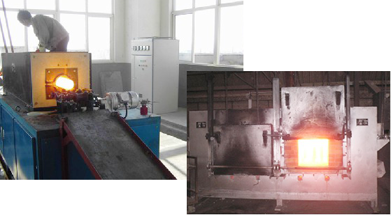
Detection method of common faults of medium frequency electric furnace
1. First, observe whether the indication values of the four small meters in the if cabinet are normal. The rectifier operated voltmeter is 30V, the rectifier pulse ammeter is 130 ~ 150mA, the inverter operated voltmeter is 12V, and the inverter pulse ammeter is 100 ~ 120mA. If the value is within the normal range, it proves that there is no problem with the power supply part.
2. Check the anode, cathode resistance, control electrode and cathode resistance of rectifier and inverter thyristor with the digital multimeter in 2008 (it is not necessary to remove it from the cabinet for measurement, and there is still cooling water in the pipe radiator). The positive and negative resistance values of anode and cathode are ∞, and the resistance values of control electrode and cathode are 10 ~ 508. In addition, check whether the fuse is blown.
3. Place the change-over switch SA in the viewing gear, use an oscilloscope to check the waveform of rectifier and inverter trigger pulse, and check whether the amplitude and time interval are normal. In the meantime, the rectifier trigger pulse is double pulse, and the time interval is 3.33ms; The inverter trigger pulse is a continuous pulse train, and the amplitude is generally 4 ~ 6V. The pulse shall be neat and free of burrs. The viewing order is from the thyristor control pole to the pulse transformer, and then to the rectifier board and inverter board.

4. Check whether the rectifier board is normal. The inverter board can be unplugged and the change-over switch can be placed in the viewing gear. Press the start button and turn the power regulating potentiometer to see if the DC voltage can be adjusted to about 500V. If the voltage can be adjusted to 500V, it proves that the rectifier board is normal.
5. Check the capacitor charging circuit in the engine circuit. Still unplug the inverter board and turn on the viewing gear. After pressing the start button, measure the voltage at both ends of the capacitor CF with a multimeter. If it can reach about 500V, it proves that the charging circuit of the starting capacitor is normal.
6. Check whether the pre magnetization resistance R6 is burnt out and whether the low-pass filter is broken.
7. If the above checks are normal, the fault can basically be the load part of the autonomous circuit. At this moment, you can check whether the capacitor has obvious burn marks or severe oil leakage, whether the insulation of the capacitor support to the ground is about 2m8, whether the water-cooling cable is burnt out, and whether the measuring induction ring has short circuit to the ground and between turns (generally caused by molten iron leakage of the furnace lining). When the induction coil is connected with water, its resistance to ground shall be more than 5k8, and the insulation resistance of the induction coil to the yoke shall be about 2m8 (when the yoke is not grounded).
8. After checking, if it is considered that the medium frequency power supply cabinet is normal, the capacitor is normal, the insulation of the induction coil and yoke meets the requirements after intermediate repair, and the furnace lining is newly built, and there is still overcurrent phenomenon in power transmission, it can be that the thermal state characteristics of an inverter thyristor are poor, that is, in the case of no power transmission, its characteristic data are normal, However, after power transmission, due to heating, there is a forced positive turn, resulting in overcurrent. At this moment, the inverter tubes should be replaced one by one to see if there is still overcurrent.
Article from:http://www.hgzqapp.com
-
11-29
Detection method of common faults of medium frequency electric furnace
1. First, observe whether the indication values of the four small meters in the if cabinet are normal. The rectifier operated voltmeter is 30V, the rectifier pulse ammeter is 130 ~ 150mA, the inverter operated voltmeter is 12V, and the inverter pulse ammeter is 100 ~ 120mA. If the value is withi
-
11-29
How to maintain the medium frequency electric furnace?
1. Regularly remove the dust in the power cabinetIn particular, the outside of the thyristor core shall be wiped clean with alcohol. The frequency conversion equipment in operation generally has a machine room, but the actual working environment is not ideal. In the smelting and forging proc
-
11-29
How to maintain the electromagnetic heating controller?
In order to ensure the uninterrupted operation of the electromagnetic heating controller, it is necessary to protect and maintain it regularly:1. Always add lubricant to the movable part of the electromagnetic brake.2. Check the length of armature stroke regularly. During the operation o
-
11-29
Causes of abnormal starting of medium frequency electric furnace
What is the cause of abnormal start of medium frequency electric furnace?Lack of phase of rectifier: the fault is that the sound is abnormal during operation, the larger output voltage rises below the rated value, and the abnormal noise announced by the power cabinet is becoming larger and l